Tag: sharma 2000

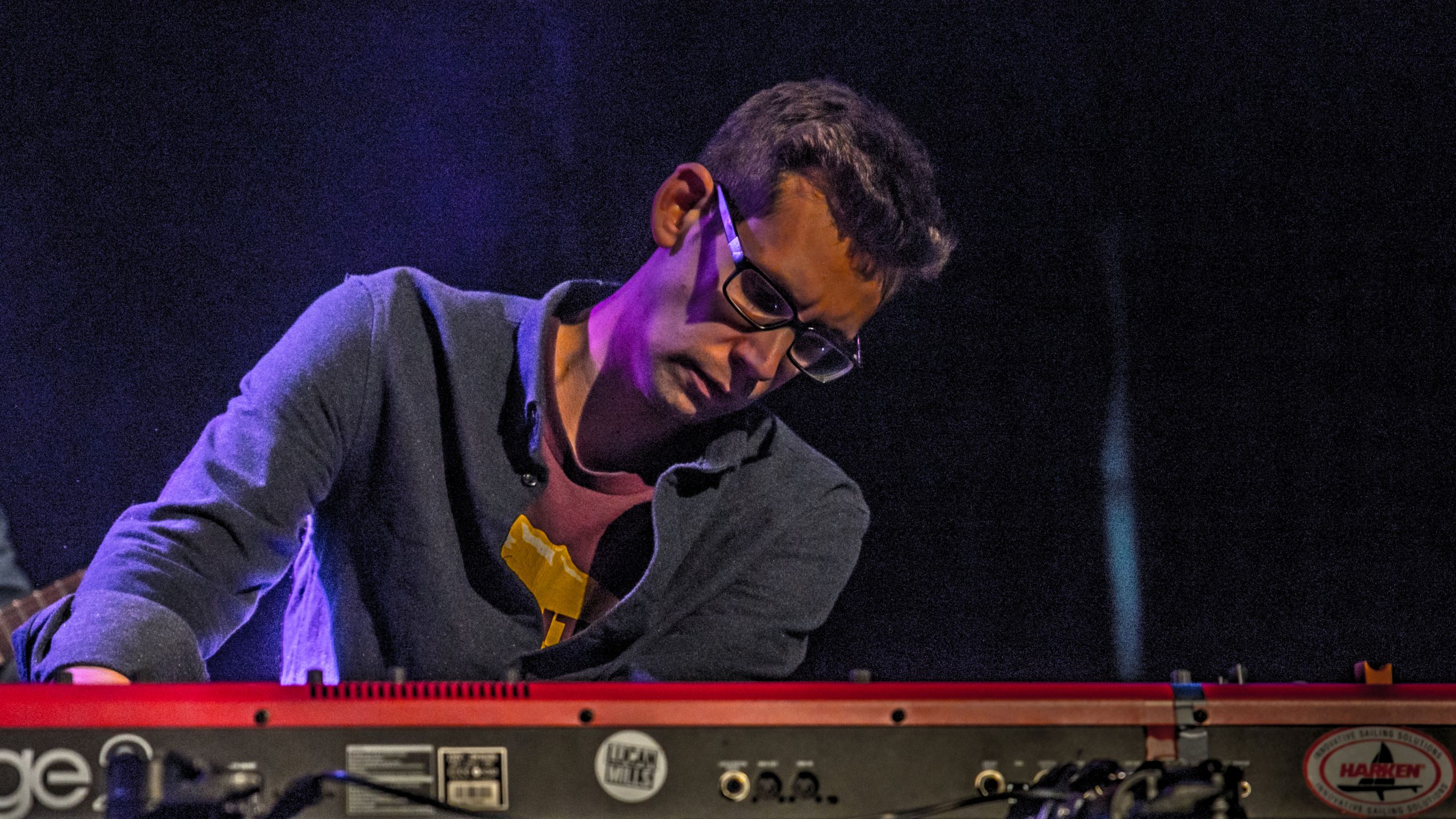
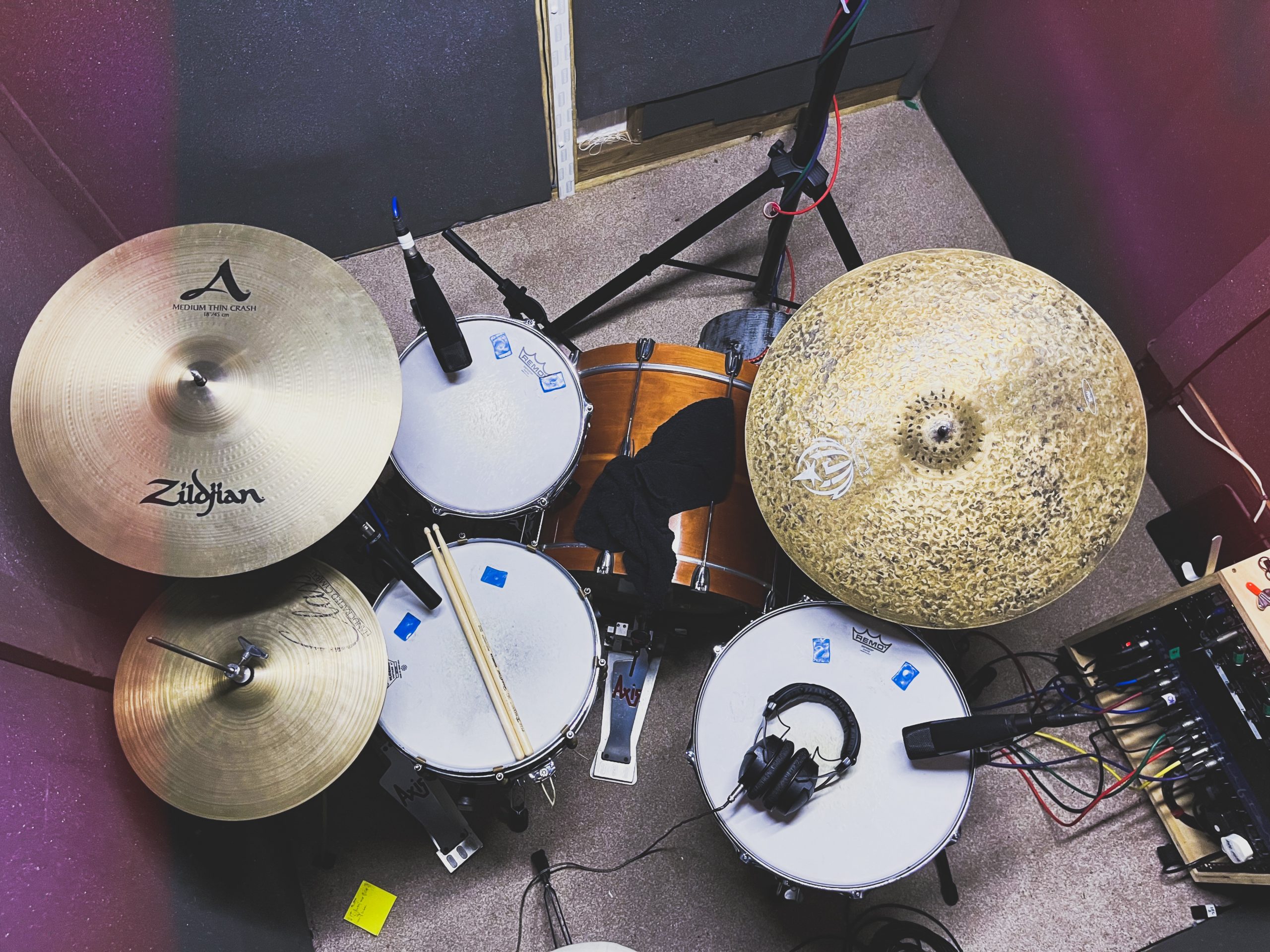
  • I’ve had the privilege of recording both drums and organs on a new single from blues singer/songwriter Alex Carter in my studio this weekend.

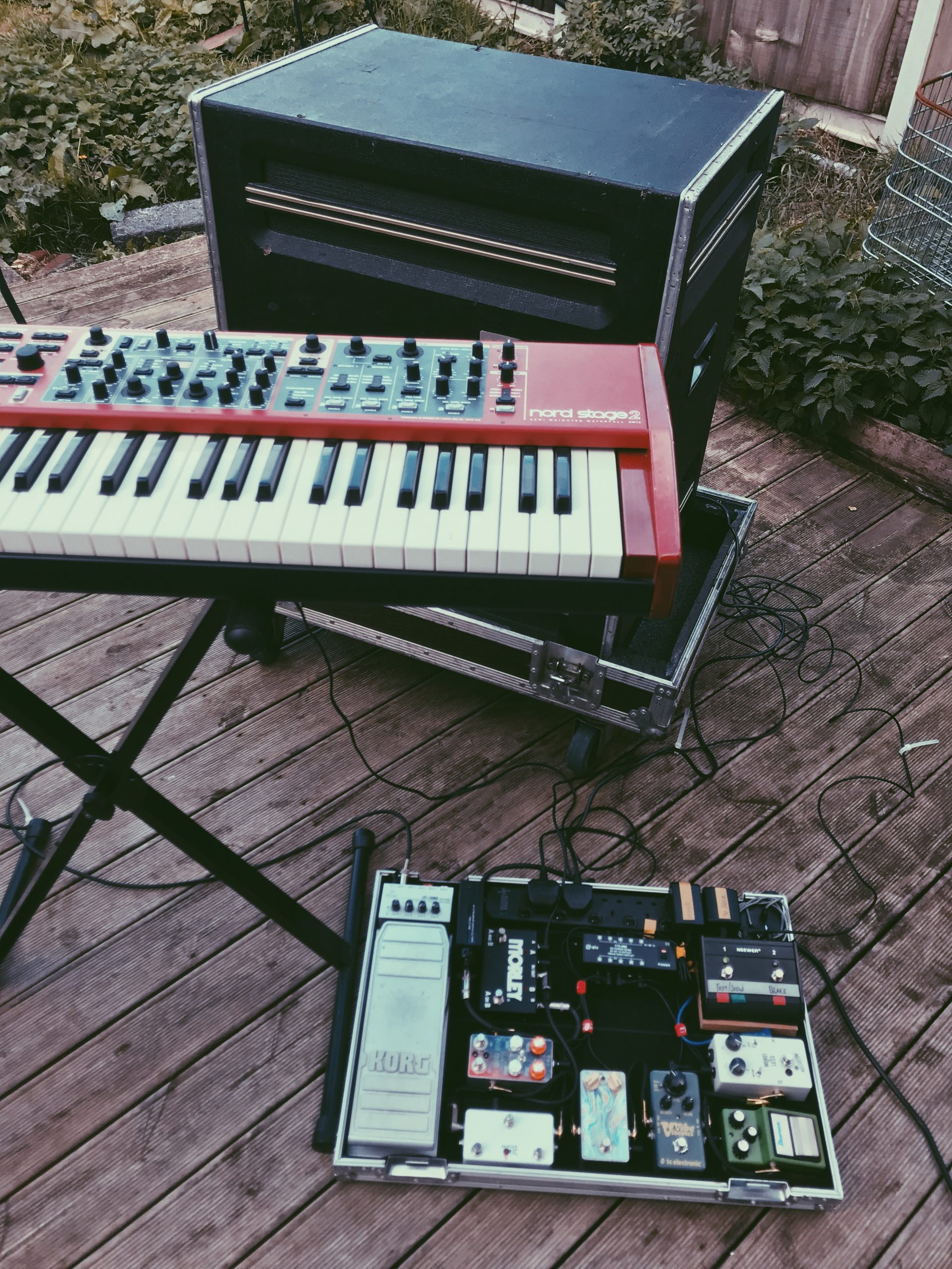
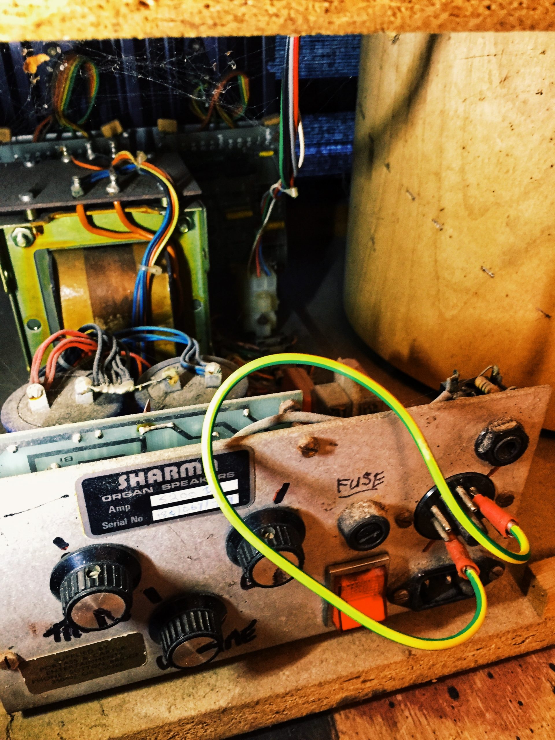
    With a super cool, groovy blues vibe, I have really enjoyed getting stuck into this session and getting the tone and feel of the song just right – both in my playing and in the choice of cymbals and studio techniques. Plus the session was also another great opportunity to run organs through my vintage Sharma 2000 rotary cab, which is always very exciting!

    Keep an eye out for the finished single being released soon. I can’t wait for everyone to hear it!

  • More Sharma 2000 Modifications

    More Sharma 2000 Modifications

    The long-awaited follow-up to my original post from January 2020 on modifying a guitar amp channel footswitch to change the motor speed in a Sharma 2000 rotary cab is finally here! I will give a small précis of the 2020 post here, for context.

    The Sharma 2000 has a nine-pin Amphenol connector on the rear panel, and three of these pins are concerned with the speed of the rotary motor; grounding Pin 6 (ie. by connecting it to Pin 1, the ground pin) spins the motor fast, whilst grounding Pin 7 spins the motor slower (and with neither pin connected to the ground of Pin 1, the motor does not spin at all). I rewired a generic footswitch to use a TRS ¼” jack connector to change which pin was connected to the ground. Because I was doing these modifications in a bit of a hurry – just a couple of days before a gig on which I planned to use the Sharma rotary speaker – I left it at that. But I always planned to return to the project at a later point and finish the job.

    Despite all the unexpected free time afforded to me by lockdowns in 2020 and 2021, I only managed to return to complete this project within the last few weeks. I decided to add bi-colour LEDs as indicators, so I could see whether the speed of the motor was set to ‘Chorale’ (slow) or ‘Tremolo’ (fast). I wanted to use green for Chorale and red for Tremolo – mimicking the LED indicators built into the Nord’s rotary speaker emulator, which also use these colours in that configuration. I also wanted to add a ‘brake’ switch to the circuit, which would stop the motor spinning altogether when activated – along with another LED, lighting up red when the brake is engaged and the motor is stopped.

    The Neewer footswitch came with small, single-colour (red) LEDs which didn’t really suit my purpose. I removed them and enlarged the holes they left to accommodate 5mm bi-colour red/green LEDs I bought on eBay. At the same time, I also drilled a hole for a 9v DC input jack so I could power the circuit for my new LEDs without needing batteries. I also removed the stock SPDT latching switches and swapped them for DPDT latching switches I had also found on eBay.

    I had to make two separate circuits inside the pedal – one to power the LEDs and switch the colour when necessary, and the other to ground Pin 6 or Pin 7 of the Sharma 2000’s Amphenol connector (or neither, when the cab is ‘braked’). I used the Fritzing app to generate a schematic for the circuits I needed (and had a little help from a friend who is far more well-versed in electronics than I am to check I was along the right lines).

    The brake switch works simply by breaking the circuit. It is inserted into the main circuit which controls the speed of the motor ahead of the switch which actually changes the speed: the sleeve of the TRS jack socket (Pin 1) goes to the one of the poles of the DPDT brake switch, with one of the throws going to one of the poles of the DPDT speed switch, and the other throw of the brake switch being a dead end which is not connected to anything. Each throw of the second DPDT switch (the speed switch) is then connected to the ring and tip of the TRS (Pin 7 and Pin 6).

    The LEDs are simply powered from the 9v DC jack, and both are connected to the other ‘half’ the DPDT switches. On the speed switcher side, the throws are wired to each cathode leg of the LED so that the red cathode leg closes the circuit when Pin 6 is grounded and the motor is spinning fast, and so that the green cathode leg closes the circuit when the switch latches the other way and Pin 7 is gounded to spin the motor slower. On the brake side, the throw which doesn’t align with closing the speed switcher circuit is wired to the red cathode leg of the LED, while the green cathode leg is unused.

    Check the video below to see the finished project in action!

  • Sharma 2000 Modifications

    Sharma 2000 Modifications

    In November I achieved a small dream of mine, as a keys player – I bought a genuine old vintage rotary cab for gigs and sessions where I’m mainly playing Hammond organ-type parts. My studio setup has evolved so that I try to stay away from emulators, and capture the sounds of real hardware and genuine components, wherever possible. So to be able to record and play live with a real rotary speaker for that sweet bluesy organ tone was a really exciting prospect for me.

    The speaker I got is a Sharma 2000 – Sharma was a British firm which was a competitor to the famous American Leslie cabs during the ’60s and ’70s. It maybe a lesser-known brand, but the Sharma speaker still sounds just like the organ tone I’ve always wanted from my playing, and put a huge grin on my face from the first moment I sat down to play organ through it. (I’m playing it from my workhorse Nord Stage 2 keyboard setup as a B3 emulator – you can’t avoid emulators altogether! – but with the Nord’s built-in rotary function switched off.)

    The Sharma speaker has the same 9-pin Amphenol connector you get on Leslies which carries input signal, volume information and various other program-change style controls. But unlike Leslies, the Sharma also has a ¼” jack line-level input and separate volume and bass/treble tone pots… So because the Nord Stage doesn’t have an Amphenol output (and the cables seem quite expensive!) I just used the line-level jack input and left the Amphenol well alone. Until I wanted to change the speed of the rotary motor inside…

    When you use the rotary emulator in the Nord, you can switch from the slow setting to the fast with a latch pedal. I use a basic Yamaha sustain pedal (the FC5) for this, and I can just stamp on it each time I want to change the rotary speed. But that is plugged directly into the keyboard, so with only the line-level output going from the Nord to the Sharma speaker there was no way for that pedal to control the speed at which the physical motor inside the Sharma cab was spinning. So I thought I’d open up the Sharma 2000 and have a look around, to see how the speed of the motor could be controlled.

    At this point, I wasn’t even sure whether you could change the speed of the motor at all; barring a skeletal Wikipedia article, I could find nothing about Sharma as a company online nor any documentation about any of their products – maybe, unlike Leslies, the Sharma rotary cabs had been built with only one possible motor speed? But I thought this unlikely, since they were designed to be competitors to Leslies, so I went exploring.

    My first step was to find out more about the 9-pin Amphenol connectors, and what they could do. If it were possible to change the motor speed whilst the speaker was in use, it would be controlled from there – probably one of its pins carried information for rotary speed. Since the Sharma was designed to compete with Leslie cabs – for which there is a lot of documentation, not to mention a thriving online community, available – I went in search of a wiring pin diagram for Amphenol connectors used in Leslie cabs.

    Typically for older engineering, it appeared that there was no standardised way to wire Amphenols for rotary speakers, and there were even variations in the numbers of pins used (some Leslie speakers being fitted with 5-pin, 6-pin, 11-pin or 12-pin versions of the connector instead) – but Uncle Harvey’s Guide To Leslie Pin-Outs proved invaluable, and I settled on a ‘most likely’ 9-pin configuration which suggested that grounding Pin 6 would result in a fast (‘tremolo’) rotary speed, whilst you grounded Pin 7 for the slow (‘chorale’) setting. The ground pin is Pin 1 – which explained why my Sharma had arrived with Pin 1 manually hardwired to Pin 6 with a small length of earth wire and a couple of cable crimps.

    Thank you, Uncle Harvey! Common 9-pin Amphenol wiring configuration in Leslie speakers
    Common 9-pin Amphenol Wiring Configuration In Leslie speakers

    I ran a couple of quick tests, manually removing the cable crimped to Pin 6 and attaching it instead to Pin 7… And, success! The motor rotated slower, for the ‘chorale’ setting. I reattached the cable to Pin 6, and the motor sped up back to ‘tremolo’ speed. But I can’t get up from the keys mid-track, go round to the back of the speaker to fiddle with a little piece of wire every time I wanted to change the organ sound; now the challenge that remained was to be able to control this change from a footswitch whilst playing a song.

    It was clear that I needed a pedal which could route a single source (ground) to one destination (Pin 6) to another (Pin 7) and back again. So unlike the momentary switching configuration of the Yamaha FC5 pedal I had been using to control the speed of the internal rotary emulator in my Nord Stage, this would need to be a single pole, double throw latching switch. Luckily this is the type of switch used in most standard guitar amp channel switching pedals – so I bought the cheapest generic guitar amp footswitch I could find which also had next-day delivery on Amazon, in the hopes of modifying it to suit my purpose in time to be able to use the Sharma 2000 (with a rotary speed switching pedal!) live on Sam Coe’s Comeback Queen album launch gig two days later.

    My cheap generic footswitch (a ‘Neewer’-branded one with a pretty standard design) arrived the next day, and I opened it up to take a look at the wiring and see how I could adapt it to suit my needs. This pedal actually has two single pole, double throw switches wired to a ¼” TRS jack socket (one for each channel on a guitar amp), but I was only going to use one of the switches as I wanted to be able to stamp on the pedal in the same place all the time to change the speed without worrying about which switch was for ‘tremolo’ and which switch was for ‘chorale’. (A classic Hammond organ setup would utilise the second switch as the ‘brake’ function – ie. stopping the motor spinning altogether – but this wasn’t a priority for me as it’s not a function I use much in my playing, so I left it blank and focused on what I needed for the show in a couple of days’ time.)

    As the Neewer pedal used a TRS jack socket to send its information – and came with a TRS jack-to-jack cable included – I needed another jack socket on the Sharma for the speed switcher input. Luckily I had some spare TRS sockets left over from another project, so I was able to just drill out a housing for it in the blank space on the panel at the rear of the cab next to where the other inputs and controls sit.

    I re-soldered the wiring inside the pedal so that the single pole of switch number one was connected to the sleeve of the TRS socket, and the tip and ring were connected to one of each of the throws, then matched this on the TRS socket I had added to the panel on the rear of the Sharma speaker by soldering the sleeve to the earth wire crimped onto Pin 1, and removing the wiring the cables from the back of Pins 6 and 7 to solder one each to the tip and ring connectors, as per my wiring diagram below.

    Wiring diagram for rotary speed controller footswitch
    Wiring Diagram For Rotary Speed Controller Footswitch

    And all that was left to do was test it. See my YouTube video below for the full process and the final result!

    And make sure to check out the video of Comeback Queen – the title track from Sam Coe’s debut solo album – live at Epic Studios in Norwich to hear the Sharma 2000 in action on a gig.

Kit Marsden // Musician