
The long-awaited follow-up to my original post from January 2020 on modifying a guitar amp channel footswitch to change the motor speed in a Sharma 2000 rotary cab is finally here! I will give a small précis of the 2020 post here, for context.
The Sharma 2000 has a nine-pin Amphenol connector on the rear panel, and three of these pins are concerned with the speed of the rotary motor; grounding Pin 6 (ie. by connecting it to Pin 1, the ground pin) spins the motor fast, whilst grounding Pin 7 spins the motor slower (and with neither pin connected to the ground of Pin 1, the motor does not spin at all). I rewired a generic footswitch to use a TRS ¼” jack connector to change which pin was connected to the ground. Because I was doing these modifications in a bit of a hurry – just a couple of days before a gig on which I planned to use the Sharma rotary speaker – I left it at that. But I always planned to return to the project at a later point and finish the job.
Despite all the unexpected free time afforded to me by lockdowns in 2020 and 2021, I only managed to return to complete this project within the last few weeks. I decided to add bi-colour LEDs as indicators, so I could see whether the speed of the motor was set to ‘Chorale’ (slow) or ‘Tremolo’ (fast). I wanted to use green for Chorale and red for Tremolo – mimicking the LED indicators built into the Nord’s rotary speaker emulator, which also use these colours in that configuration. I also wanted to add a ‘brake’ switch to the circuit, which would stop the motor spinning altogether when activated – along with another LED, lighting up red when the brake is engaged and the motor is stopped.
The Neewer footswitch came with small, single-colour (red) LEDs which didn’t really suit my purpose. I removed them and enlarged the holes they left to accommodate 5mm bi-colour red/green LEDs I bought on eBay. At the same time, I also drilled a hole for a 9v DC input jack so I could power the circuit for my new LEDs without needing batteries. I also removed the stock SPDT latching switches and swapped them for DPDT latching switches I had also found on eBay.
I had to make two separate circuits inside the pedal – one to power the LEDs and switch the colour when necessary, and the other to ground Pin 6 or Pin 7 of the Sharma 2000’s Amphenol connector (or neither, when the cab is ‘braked’). I used the Fritzing app to generate a schematic for the circuits I needed (and had a little help from a friend who is far more well-versed in electronics than I am to check I was along the right lines).
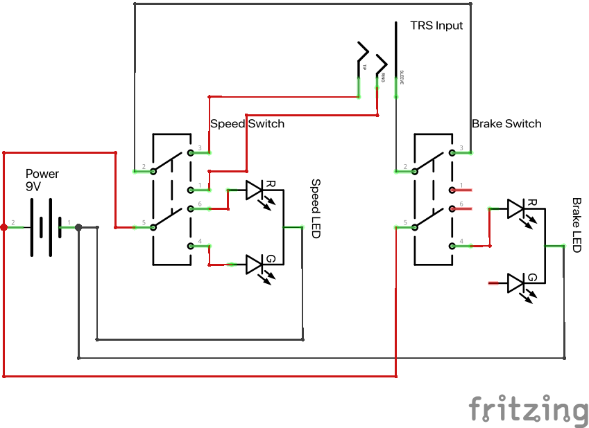
The brake switch works simply by breaking the circuit. It is inserted into the main circuit which controls the speed of the motor ahead of the switch which actually changes the speed: the sleeve of the TRS jack socket (Pin 1) goes to the one of the poles of the DPDT brake switch, with one of the throws going to one of the poles of the DPDT speed switch, and the other throw of the brake switch being a dead end which is not connected to anything. Each throw of the second DPDT switch (the speed switch) is then connected to the ring and tip of the TRS (Pin 7 and Pin 6).
The LEDs are simply powered from the 9v DC jack, and both are connected to the other ‘half’ the DPDT switches. On the speed switcher side, the throws are wired to each cathode leg of the LED so that the red cathode leg closes the circuit when Pin 6 is grounded and the motor is spinning fast, and so that the green cathode leg closes the circuit when the switch latches the other way and Pin 7 is gounded to spin the motor slower. On the brake side, the throw which doesn’t align with closing the speed switcher circuit is wired to the red cathode leg of the LED, while the green cathode leg is unused.
Check the video below to see the finished project in action!

Leave a Reply